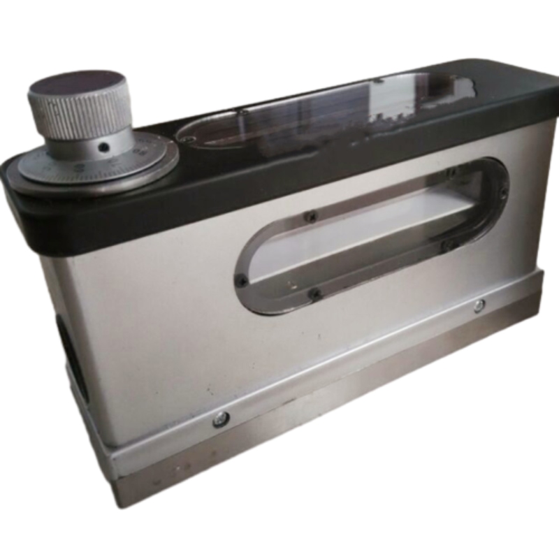
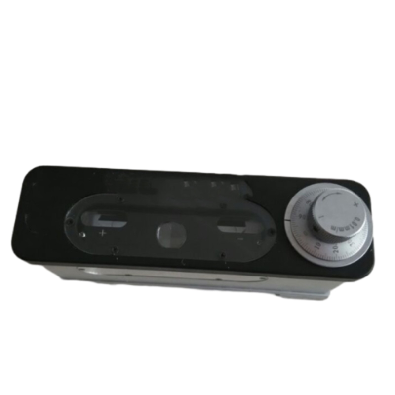
Nivel de imagen compuesta óptica
Descripción del Producto
- 1.Aplicación
El nivel de imagen compuesta óptica se usa ampliamente para medir los gradientes de superficies planas y superficies cilíndricas en dirección horizontal; La planicidad y rectitud de la guía deslizante o base de la máquina herramienta o instrumento mecánico óptico, así como la corrección de la posición de instalación del equipo.
- 2.Datos técnicos
(1) cada valor de graduación: ...0,01 mm/m
(2) rango de medición máximo: ...0~10 mm/m
(3) tolerancia: ...1 mm/dentro de un metro... 0,01 mm/m
Dentro del rango de medición completo...0,02 mm/m
(4) desviación del plano en la superficie de trabajo...0,0003 mm/m
(5) cada valor de graduación del nivel de burbuja...0,1 mm/m
(6) superficie de trabajo (LW): ...165 48mm
(7) peso neto del instrumento: ...2kgs.
- 3.Estructura del instrumento:
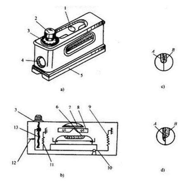
El nivel de imagen compuesta consta principalmente de las siguientes piezas, como tornillo de microajuste, tuerca, disco graduado, nivel de burbuja, prisma, lupa, palanca y base con superficie de trabajo plana y en V.
- 4.Principio de funcionamiento:
El nivel de imagen compuesta utiliza un prisma para obtener imágenes de burbujas de aire en el compuesto de nivel de burbuja y se magnifica para mejorar la precisión de la lectura y utiliza un sistema de transmisión de palanca y microtornillo para mejorar la sensibilidad de lectura. Por lo tanto, si la pieza de trabajo tiene un gradiente de 0,01 mm/m, se puede leer con precisión en el nivel de imagen compuesta (el nivel de burbuja en el nivel de imagen compuesta desempeña principalmente el papel de indicar cero).
- 5.Método de funcionamiento:
Coloque el nivel de imagen compuesta sobre la superficie de trabajo de la pieza de trabajo de medición y el gradiente de la pieza de trabajo de medición provocará que las imágenes de las burbujas de aire no coincidan; Gire el disco graduado hasta que las imágenes de las burbujas de aire coincidan y se pueda obtener la lectura inmediatamente. La pendiente real de la pieza de medición se puede calcular mediante la siguiente fórmula:
Gradiente real = valor del gradiente Distancia de fulcro Lectura del disco
Ejemplo de Fox: Lectura de disco: 5 gradientes; Como este nivel de imagen compuesta está confundido con su valor de gradiente y distancia de punto de apoyo, es decir, valor de gradiente: 0,01 mm/m y distancia de punto de apoyo: 165 mm.
Entonces: gradiente real = 165 mm 5 0,01/1000 = 0,00825 mm
- 6. Aviso de operación:
(1) antes de usar, limpie el polvo de aceite con gasolina y luego limpie con una gasa absorbente.
(2) El cambio de temperatura tiene una gran influencia en el instrumento y, por lo tanto, debe separarse con una fuente de calor para evitar errores.
(3) Durante la medición, gire el disco graduado hasta que las imágenes de las burbujas de aire coincidan completamente y luego se podrán tomar lecturas en direcciones positivas y negativas.
(4) If the instrument is found with in correct zero position, it may be adjusted; Put the instrument on a stable table and rotate the graduated disc to set the tow air bubble images coincide to get first reading a; Then turn the instrument by 180o and put back to its original place. Ra-rotate the graduated disc to get the tow air bubbles coincide to get the second reading b. So 1/2 (α +β ) is the zero deviation of the instrument. Loosen the three supporting screws on the graduated disc and press lightly by hand the embossed adjusting cap; Rotate the disc by 1/2 (α +β) to get the zero deviation and the point line composite; At last fasten the screws.
(5) Después del trabajo, la superficie de trabajo del instrumento debe limpiarse y recubrirse con aceite antioxidante anhidro, libre de ácido y papel antioxidante; Colóquelo en una caja de madera y luego guárdelo en un lugar limpio y seco.
Hot Tags: Optical Composite Image Level Optical Composite Image Level suppliers China Optical Composite Image Level Optical Composite Image Level factory stable Optical Composite Image Level
Parámetro del producto
Parámetros técnicos
- Dial de valor de placa 0,01 mm/m
- Rango de medición 0-10 milímetros/metro
- Parent-child error within ± 1mm/m+0.01 mm/m
- The parental error within the entire measurement range is ± 0. 02 millimeters/meter
- Desviación de la planitud del banco de 0,003 mm
- Estándar de acumulación de valor de celda 0,1 milímetros/metro
- Tamaño del escritorio de oficina 165 x 48 milímetros
- Peso neto 2,2 kilogramos
Optical Composite Image Level Maintenance: Antirust Oil & Storage Tips
Proper maintenance ensures your optical composite image level retains its 0.01mm/m precision and durability. Follow these steps to protect its prism technology and mechanical components:
1. Daily Cleaning for Surface Protection
After use, wipe working surfaces (V-groove, edges, lenses) with isopropyl alcohol on a lint-free cloth to remove oils and dust. Use a soft brush for stubborn debris—never abrasives, which can scratch optical parts or damage metal coatings. This preserves the precision ground surfaces (Ra ≤ 0.1μm) critical for accurate readings.
2. Routine Antirust Care for Metal Parts
While the granite base resists corrosion, metal components (screws, levers, hinges) need protection. Apply Storaen’s non-acidic anti-rust oil every 3 months or after moisture exposure:
Apply thinly to threads and pivots with a dropper, avoiding pooling on granite/lenses.
Prevents seizing: Maintains lever mechanism sensitivity (0.001mm precision) for cylindrical slope measurements.
3. Optimal Storage Practices
Store in the included hard case or a dry cabinet to avoid temperature/humidity damage:
Environment: 10°C–30°C, <60% humidity to prevent lens condensation and optical distortion.
Positioning: Lay flat or upright in padded slots; never under heavy objects to avoid misaligning the optical system.
Long-term storage: Reapply anti-rust oil and add a silica packet; inspect 24 hours before use, verifying zero position via 180° rotation calibration.
4. Monthly Functional Inspections
Check performance regularly to ensure reliability:
Bubble clarity: Confirm the composite bubble image aligns smoothly without blur.
Lever movement: Test micro-screws for smooth rotation—stiffness signals needed lubrication.
Flatness check: Use a reference plate to validate factory-calibrated flatness (±0.0003mm/m).
5. Storaen’s Support for Longevity
Leverage our expert services to maintain peak performance:
Factory recalibration: Restores 0.01mm/m precision via ISO-certified equipment for critical applications.
Genuine parts: Replacement components ensure compatibility and preserve original accuracy.
By following these steps, your Storaen optical composite image level will deliver consistent precision for industrial alignment tasks, backed by our 30+ years of engineering expertise.
Zero Position Calibration of Optical Composite Image Level: 180° Rotation Method Explained
Accurate zero calibration is vital for your Storaen optical composite image level to maintain its 0.01mm/m precision and ±0.0003mm/m flatness. The 180° rotation method eliminates subtle optical or mechanical shifts, ensuring reliable measurements in critical tasks like CNC machine alignment or aerospace component inspection. Here’s a streamlined, step-by-step guide:
1. Why Calibrate?
Impacts, vibrations, or temperature fluctuations can shift the level’s zero reference, leading to measurement drift. Calibration realigns the bubble vial with the tool’s optical prism and lever system, ensuring consistent baselines for industrial applications where 0.001mm deviations are unacceptable—such as verifying machine tool guides or structural frameworks.
2. Setup Requirements
Storaen optical composite image level (featuring a V-grooved base and micro-adjusting screw)
Certified precision reference flat (e.g., our Storaen granite surface plate, with flatness ≤0.0002mm/m)
A clean, vibration-free workbench in a temperature-stabilized environment (18°C–22°C recommended)
3. Step 1: Initial Measurement
Place the level lengthwise on the reference flat, aligning the V-grooved base with the flat’s central axis. Rotate the micro-adjusting screw until the composite bubble image—created by the 45° prism system—perfectly overlaps in the viewfinder. Record this initial scale reading (A), which reflects the current deviation from true zero.
4. Step 2: 180° Rotation & Second Reading
Carefully flip the level 180° end-to-end while maintaining its longitudinal orientation on the flat (avoid any lateral movement). Adjust the micro-screw again to align the bubble image and record the new reading (B). The difference Δ = |A - B| indicates zero position error; ideal values for Storaen levels should be ≤0.005mm/m.
5. Step 3: Error Correction & Verification
Calculate the target zero position as the midpoint: C = (A + B)/2. Loosen the protective cap on the zero-adjustment screw (typically located near the bubble vial), rotate the screw until the scale reads C, then retighten. Repeat Steps 3–4 until Δ ≤0.002mm/m, ensuring minimal residual error.
6. Pro Tips for Precision
Triple-Check Consistency: Perform 3 calibration cycles, especially after transporting the level or working in environments with temperature swings, to ensure repeatable results.
Lubricate Moving Parts: Apply a drop of Storaen’s non-acidic oil to the micro-screw before adjustment to ensure smooth, backlash-free operation and prevent binding.
Environmental Control: Avoid calibrating near heat sources or drafts, as even minor temperature gradients can affect the granite base’s dimensional stability and introduce errors.
7. Storaen’s Calibration Support
Every Storaen optical composite image level includes a NIST-traceable calibration certificate, but quarterly in-field checks are recommended for heavy use. Our support includes:
Factory Recalibration: Restoring original 0.01mm/m accuracy using laser interferometers for high-stakes applications.
Genuine Spare Parts: Readily available adjustment screws and maintenance kits for long-term usability.
Video Tutorials & Expert Guidance: Step-by-step videos and engineer support to assist with on-site calibration procedures.
Final Notes
Mastering the 180° rotation method ensures your Storaen optical composite image level delivers the precision required for cylindrical slope measurements, machine tool flatness checks, and other critical alignments. With proper calibration, this tool, backed by our 30+ years of engineering expertise, becomes an indispensable asset in your quality control workflow, ensuring every measurement is as reliable as the first.
Relacionado PRODUCTOS
NOTICIAS RELACIONADAS
Thread Plug Gauge Requires Careful Handling
In the world of manufacturing and engineering, precision is non-negotiable—especially when it comes to threads, which are critical components in machinery, construction, and everyday products.
Surface plate calibration
In today's world, where precision and accuracy are crucial in various industries, the use of granite inspection tables and granite surface plates has become increasingly popular.
Ring Gauge Ensures Machining Accuracy
In the world of precision engineering, manufacturing, and quality control, accuracy is the cornerstone of reliability.
